Building My ESP32 Smart Switch: From Prototype to Custom Hardware
How I built an ESP-based Wi-Fi smart switch, from early hardware experiments to relay control, firmware, debugging, and custom PCB design.
Introduction: Beyond the LED Blink Demo
Almost every beginner's journey into microcontrollers begins with an LED. You connect a 220Ω resistor to a digital output pin on an Arduino or ESP board, call digitalWrite(pin, HIGH), and watch a tiny light emit a steady glow.
While that first blinking diode is exciting, it doesn't solve a real problem in the physical world. In a real home, nobody controls miniature 5-milliamp LEDs. We live with high-voltage alternating current: 230-volt ceiling fans, heavy tube lights, room heaters, and appliances switched through thick copper wires behind plastic wall switchboards.
More importantly, most internet-of-things (IoT) smart switches sold commercially have an infuriating flaw: they are slaves to the cloud.
If your broadband connection drops, if the home Wi-Fi router reboots, or if a third-party server suffers an outage, your smart lights stop responding. Even worse, many commercial smart modules ignore existing mechanical wall switches entirely. When your family members flip the switch on the wall, the app loses sync, and nobody knows whether the circuit is truly open or closed.
I built Smart Switch because I wanted to solve this problem from an engineering standpoint. I wanted to build an embedded home automation system grounded in an uncompromising offline-first philosophy:
- Physical wall switches must always work, with or without Wi-Fi.
- Power cuts must not cause unpredictable relay toggling.
- The device must host its own local web interface so smartphones can control appliances directly without third-party internet dependencies.
- The system must transition responsibly from a breadboard prototype toward a robust hardware architecture.
Here is the story of how I built it—from early microcontroller experiments to multi-channel relay logic, firmware architecture, serial telemetry, and hardware design.
Why I Wanted to Build a Smart Switch
Living and building projects in Teghra, Bihar, the reality of everyday electrical infrastructure is immediate. Power interruptions happen, voltage fluctuations occur, and mobile data or Wi-Fi connectivity is not always 100% stable.
In this environment, a smart switch that relies entirely on a remote cloud server is practically unusable. Imagine walking into a dark room during an internet outage and not being able to turn on a light because a cloud handshake timed out. That isn't smart home technology—it's a regression.
My design criteria were clear from day one:
- Zero-Latency Physical Control: Toggling a household wall switch must trigger the relay instantly (under 20 milliseconds), completely debounced and immune to electrical contact bounce.
- Deterministic Boot-Time State Sync: When electricity returns after a power outage, the microcontroller must immediately read the physical switches and restore the exact expected state.
- Local-First Network Control: The device must host an onboard asynchronous web server and captive portal so any phone on the local network can access a control dashboard without an active internet connection.
- Galvanic Isolation: The low-voltage digital brain must remain strictly isolated from 230V mains current.
Starting with the ESP: Early Experiments & Powering
Before building a full 4-channel household system, I started with fundamental hardware experiments using the ESP architecture.
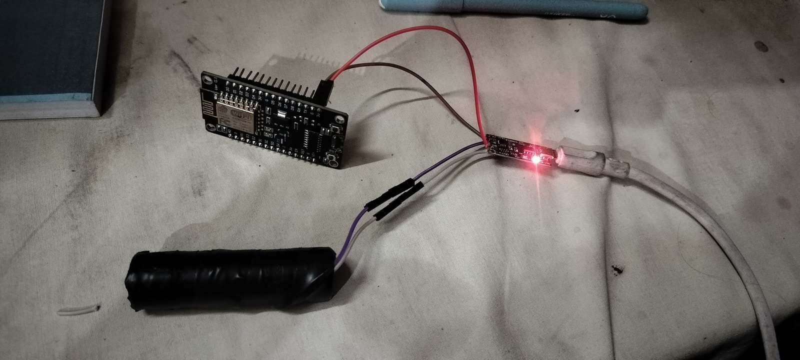
My initial explorations in late 2025 focused on understanding microcontroller behavior under real-world conditions:
- Power Rail Stability: Powering an ESP module through battery rails (using a TP4056 charging circuit and single-cell lithium battery) taught me how sensitive microcontrollers are to voltage sag during Wi-Fi transmission bursts. When an ESP chip transmits RF packets, current draw can spike up to 300–400mA for brief microseconds. Without adequate decoupling capacitors across the 3.3V rail, brownout resets trigger instantly.
- Bootloader Dynamics: Observing how different GPIO pins behave during boot. Certain pins on ESP chips are "strapping pins"—if pulled LOW or HIGH during the brief microsecond window when the chip powers on, the microcontroller enters download bootloader mode instead of executing application firmware.
These preliminary experiments provided the foundation I needed before connecting microcontrollers to real mechanical relays and household switches.
Making a Real Relay Control System
Controlling a high-voltage household appliance requires an electromechanical relay. A relay functions as an electrically operated magnetic switch: a low-power 5V control coil pulls an armature down, mechanically connecting the high-voltage common terminal (COM) to the normally open terminal (NO).
  [ ESP32 3.3V GPIO ]
           │
           ▼
  [ Optocoupler LED ] ── (Optical Air Gap) ──► [ Phototransistor ]
                                                       │
                                                       ▼
                                              [ NPN Driver Circuit ]
                                                       │
                                                       ▼
                                              [ 5V Relay Coil + Diode ]
                                                       │
                                                       ▼
                                         [ 230V AC Mechanical Contacts ]
                                         (Galvanically Isolated Mains)
For Smart Switch, I utilized a 4-Channel 5V Relay Module equipped with Songle SRD-05VDC-SL-C relays rated for switching AC loads up to 250V / 10A.
The Active-LOW Relay Trap
Most commercial hobbyist relay boards are Active-LOW. This means:
- Driving the input pin LOW (0V) completes the optocoupler circuit, energizing the coil and turning the relay ON.
- Driving the input pin HIGH (3.3V/5V) turns the optocoupler off, de-energizing the coil and turning the relay OFF.
This presents an immediate engineering danger: when an ESP32 boots, default GPIO configurations can momentarily float or default to LOW. If your firmware isn't written defensively, every relay will click ON the instant power is applied!
To prevent this in Smart Switch, I architected the RelayController class to enforce a guaranteed safe boot state:
// src/control/relay_controller.cpp
#define RELAY_ACTIVE_LOW true

void RelayController::begin() {
    LOG_RELAY("Initializing relay controller");

    /* Configure relay pins as outputs */
    pinMode(RELAY_1_PIN, OUTPUT);
    pinMode(RELAY_2_PIN, OUTPUT);
    pinMode(RELAY_3_PIN, OUTPUT);
    pinMode(RELAY_4_PIN, OUTPUT);

    /* Immediately assert safe OFF state before enabling inputs */
    // In Active-LOW logic: HIGH = Relay OFF
    digitalWrite(RELAY_1_PIN, RELAY_ACTIVE_LOW ? HIGH : LOW);
    digitalWrite(RELAY_2_PIN, RELAY_ACTIVE_LOW ? HIGH : LOW);
    digitalWrite(RELAY_3_PIN, RELAY_ACTIVE_LOW ? HIGH : LOW);
    digitalWrite(RELAY_4_PIN, RELAY_ACTIVE_LOW ? HIGH : LOW);

    LOG_OK("All relays set to OFF (safe state)");
}
By writing HIGH to every relay pin during initialization, the firmware ensures zero false clicks or load toggles during startup.
The Physical Switch Problem & Real Bench Setup
The defining challenge of smart home design is reconciling mechanical switches with software control.
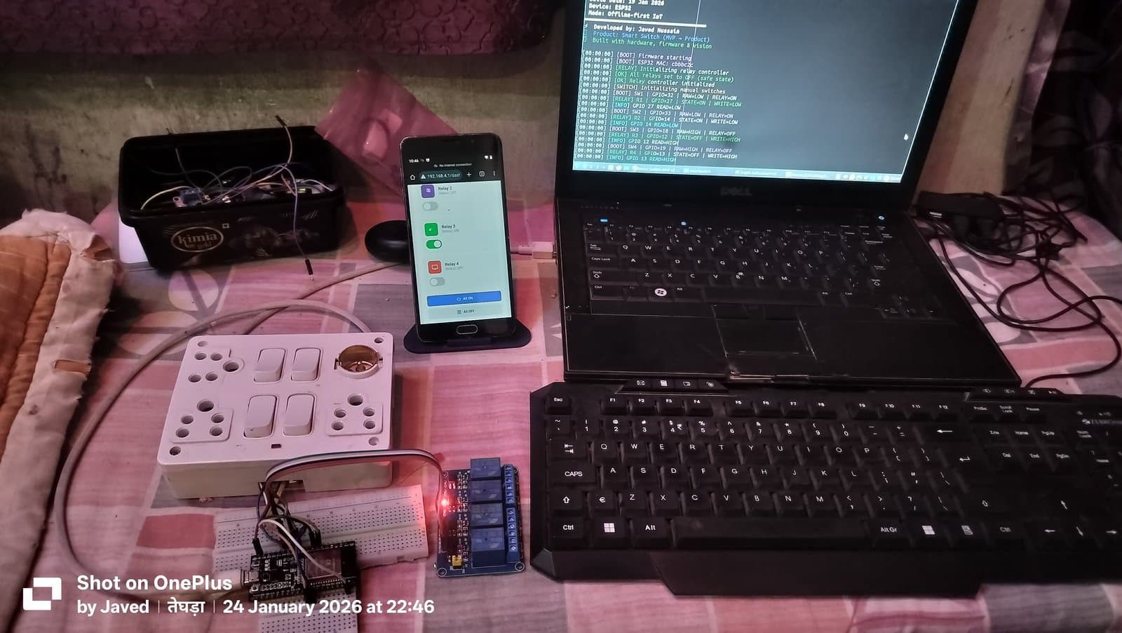
In a normal home, when someone turns on a light switch, the circuit is closed. If your smart system only accepts software toggles, physical wall switches become useless. To solve this, I built a dedicated physical test bench using a standard Indian household 4-gang modular switchboard:
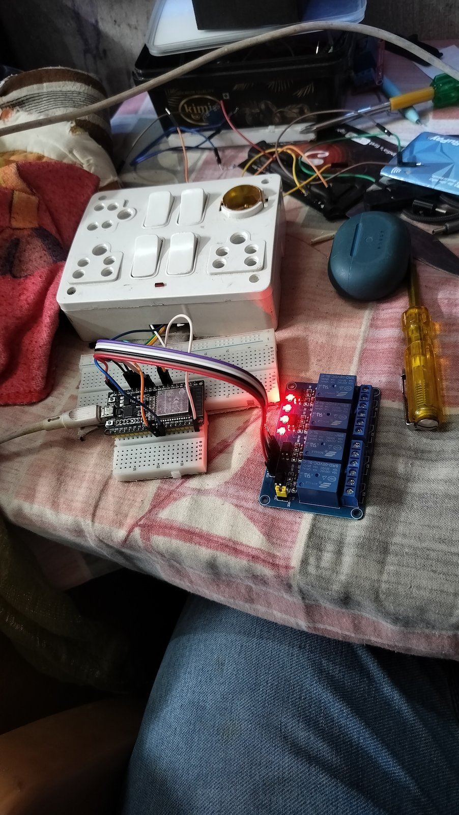
Low-Voltage Signal Wiring
Instead of routing dangerous 230V AC through the wall switch contacts to the microcontroller, the wall switches are wired exclusively as low-voltage digital logic inputs:
- Each mechanical switch connects between one ESP32 GPIO and common GND.
- The ESP32 configures each pin with an internal pull-up resistor (
INPUT_PULLUP). - When the wall switch is open, the pin reads
HIGH(3.3V). - When the wall switch is closed, the pin is pulled to ground and reads
LOW(0V).
Non-Blocking Debounce Engine
Mechanical switches are spring-loaded metal contacts. When you flick a switch, the contacts bounce against each other for 5 to 20 milliseconds before settling into continuous contact. If a microcontroller reads that raw pin directly, it will register dozens of rapid ON/OFF triggers in a fraction of a second.
In manual_switch.cpp, I implemented a non-blocking debouncing state machine utilizing millis():
// src/control/manual_switch.cpp
void ManualSwitch::update() {
    for (int i = 0; i < 4; i++) {
        bool reading = digitalRead(switchPins[i]);

        /* Detect raw edge transition */
        if (reading != lastReadState[i]) {
            lastDebounceTime[i] = millis();
            lastReadState[i] = reading;

            LOG_SWITCH("SW" + String(i + 1) +
                       " | GPIO=" + String(switchPins[i]) +
                       " | RAW -> " + (reading == HIGH ? "HIGH" : "LOW"));
        }

        /* Verify stable state after debounce window */
        if ((millis() - lastDebounceTime[i]) > debounceDelay) {
            if (reading != lastStableState[i]) {
                lastStableState[i] = reading;

                // Active-LOW input: LOW reading = switch engaged
                bool relayState = (reading == LOW);

                LOG_SWITCH("SW" + String(i + 1) +
                           " | STABLE=" + (reading == HIGH ? "HIGH" : "LOW") +
                           " | CMD RELAY=" + (relayState ? "ON" : "OFF"));

                relay.setRelay(i + 1, relayState);
            }
        }
    }
}
Safe GPIO Selection: A Crucial Hardware Discovery
One of the most valuable lessons I learned during the prototype build came from selecting GPIO pins.
On an ESP32 with 30 or 38 exposed pins, beginners often assume every pin labeled "GPIO" can be used interchangeably for any input or output. That assumption can break hardware quickly.
The Hard Truth About GPIO 34–39
In my initial pin layout planning, I considered using pins 34 and 35 for manual switches because they were located near the ground rail. However, during testing, the inputs floated unpredictably, triggering random ghost switches even when nobody touched the board.
Upon reviewing the Espressif ESP32 technical reference manual, I discovered the root cause:
GPIO 34, 35, 36, and 39 (GPI pins) are INPUT-ONLY pins and DO NOT possess internal pull-up or pull-down resistors.
Calling pinMode(34, INPUT_PULLUP) fails silently in hardware because the internal pull-up resistor silicon simply does not exist on those silicon channels!
To establish rock-solid stability, I restructured the pin configuration entirely:
- Manual Switches (INPUT_PULLUP): GPIO 32 (Yellow), GPIO 33 (Green), GPIO 18 (Orange), GPIO 19 (Blue).
- Relay Outputs: GPIO 27, GPIO 14, GPIO 12, GPIO 13.
- Status LED: GPIO 15 (with current-limiting resistor).
This clean separation eliminated floating inputs and created a deterministic hardware layer.
Boot-Time State Synchronization
Consider this scenario: you go to sleep with your bedroom light switch turned OFF. At 3:00 AM, the local power grid suffers a blackout. Thirty minutes later, electricity is restored.
What should your smart switch do?
In poorly architected smart devices, the microcontroller boots up, defaults its relays to ON, or waits endlessly for a cloud connection to figure out what state it was in. The result? Your bedroom lights turn on full blast in the middle of the night.
In Smart Switch, I engineered deterministic boot-time state synchronization:
- During
boot_manager.cppexecution, the firmware asserts safeHIGHon all relay outputs. - The
ManualSwitch::begin()routine immediately performs adigitalReadon all 4 physical wall switch inputs. - If Switch 1 is physically in the ON position, Relay 1 is commanded ON. If it is physically OFF, Relay 1 remains OFF.
The relays reflect the physical reality of the room within 50 milliseconds of boot—without waiting for Wi-Fi, without consulting a server, and without user intervention.
Connecting the Switch to Wi-Fi: Captive Portal & Local Control
Once the physical switching was bulletproof, I layered on the wireless capabilities.
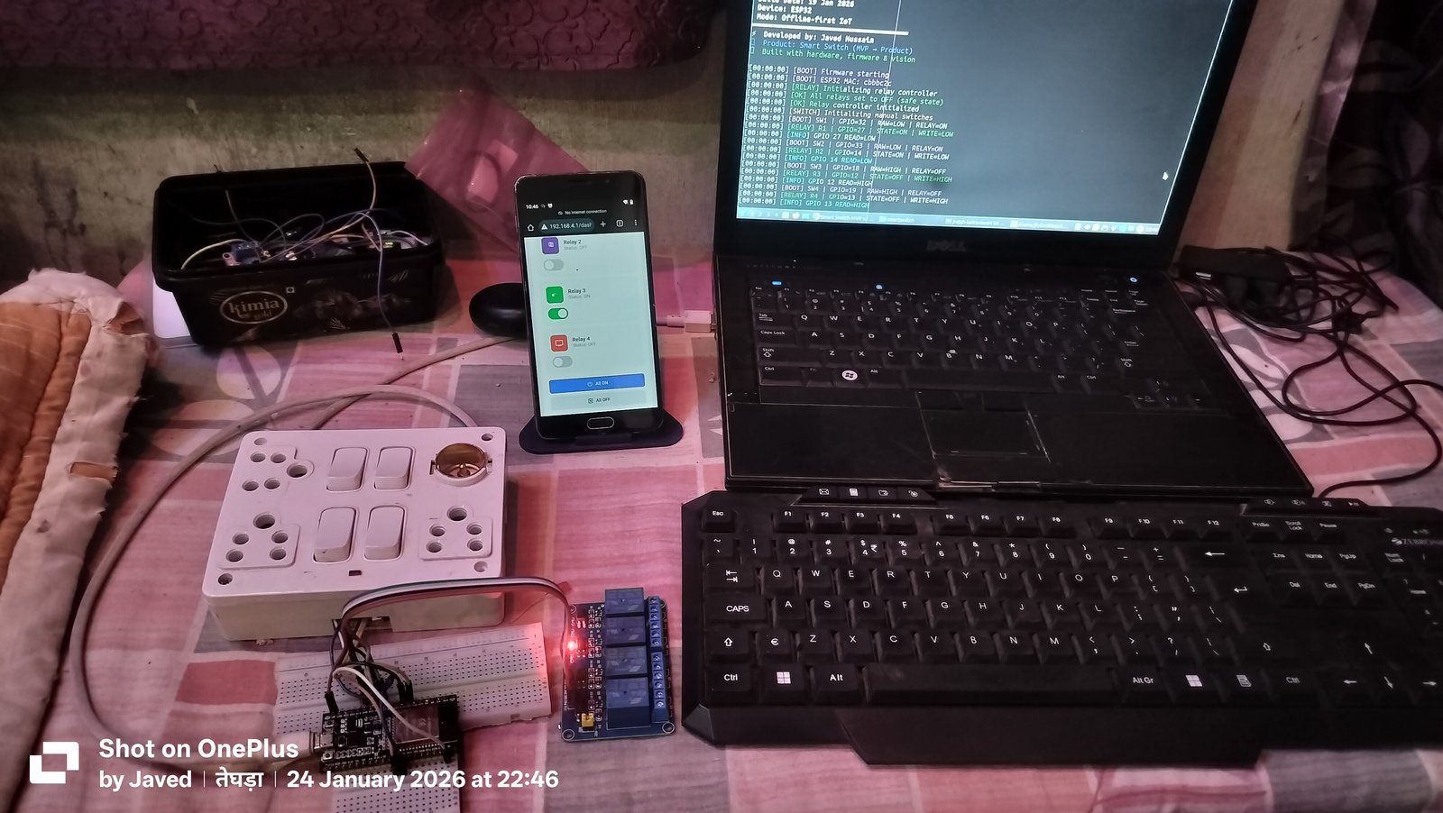
Instead of requiring users to download a heavy mobile app from an app store, Smart Switch runs an embedded asynchronous HTTP web server (ESPAsyncWebServer) directly on the ESP32:
1. Captive Portal AP Mode (SmartSwitch-AP)
If the switch is not yet configured with home Wi-Fi credentials, it boots into Access Point (AP) mode. When you connect your smartphone to the open SmartSwitch-AP network, a captive portal automatically redirects your browser to:
http://192.168.4.1/dash
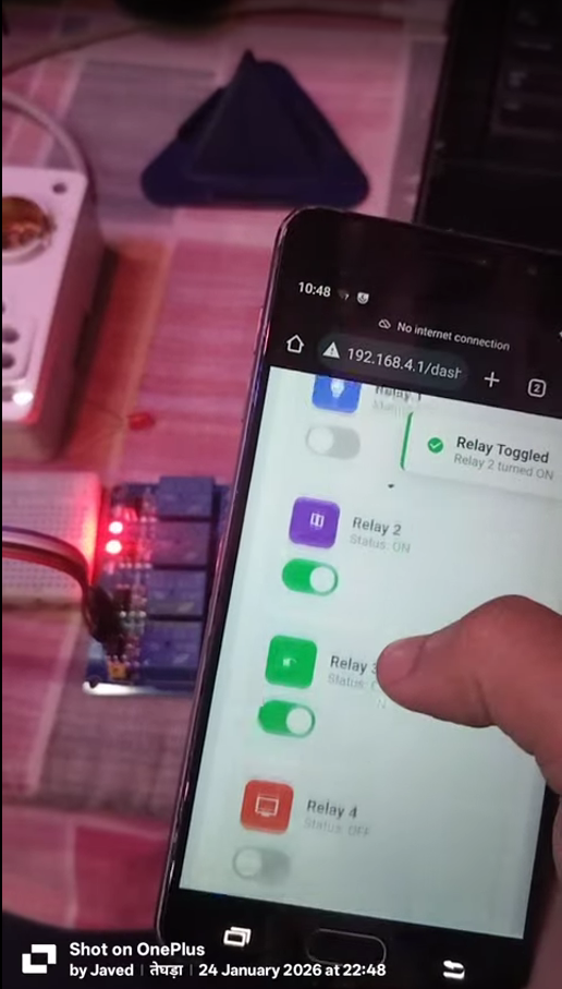
2. Live Web Dashboard
The dashboard is served entirely out of ESP32 flash memory as compressed HTML5, CSS, and JavaScript. It provides:
- Individual toggle controls for Relays 1 through 4 with live status tags.
- Master All ON and All OFF action buttons.
- A built-in Wi-Fi network scanner (
/api/wifi-scan) that searches for local 2.4 GHz access points, displaying signal strength (RSSI) bars and encryption status. - Wi-Fi credential provisioning (
/api/wifi-connect) that securely writes network credentials to Non-Volatile Storage (NVS).
3. Local Network Resolution via mDNS
Once enrolled in the home Wi-Fi network, the device joins Station (STA) mode and registers with the local multicast DNS daemon:
http://smartswitch.local
Family members can control household appliances from any laptop, tablet, or phone connected to the home Wi-Fi simply by navigating to smartswitch.local, completely bypassing the public internet.
ESP32 vs. ESP8266: Why I Standardized on ESP32
During early planning, I evaluated whether to build Smart Switch around the ubiquitous ESP8266 (NodeMCU / ESP-12F) or the newer ESP32.
While the ESP8266 is lower cost, hands-on development revealed significant constraints:
- Limited Usable GPIOs: The ESP8266 has very few safe GPIOs that do not interfere with serial programming, boot modes, or onboard flash memory. Running 4 manual switch inputs, 4 relay outputs, status LEDs, and recovery buttons simultaneously is nearly impossible on an ESP8266 without external I2C port expanders (like the PCF8574).
- Single-Core Bottleneck: On an ESP8266, running an asynchronous web server, Wi-Fi networking, software debouncing, and cryptographic routines on a single core frequently leads to watchdog timer resets if a network packet blocks execution.
- ESP32 Dual-Core Advantage: The ESP32's dual-core Xtensa processor allows clean task partitioning: one core handles high-throughput Wi-Fi networking and HTTP requests, while the second core focuses on real-time GPIO polling and debouncing.
For a 4-channel production-grade smart switch, the ESP32 proved to be the superior and far more reliable architectural choice.
Modular Firmware Architecture
Rather than dumping hundreds of lines of code into a single chaotic .ino sketch, I organized the firmware into a production-minded, modular directory structure under PlatformIO:
smart-switch-firmware/
├── platformio.ini         # Environment, baud rates, and library dependencies
├── src/
│   ├── config/            # pin_config.h, device_config.h, build_config.h
│   ├── control/           # manual_switch.cpp, relay_controller.cpp
│   ├── core/              # boot_manager.cpp, state_manager.cpp
│   ├── network/           # wifi_manager.cpp, captive_portal.cpp, mdns.cpp
│   ├── storage/           # nvs_manager.cpp (Preferences library)
│   ├── system/            # logger.cpp, watchdog.cpp, auth.cpp
│   ├── ui/                # led_manager.cpp, button_manager.cpp
│   ├── web/               # web_server.cpp (ESPAsyncWebServer routes)
│   └── webpages/          # dashboard_page.h, login_page.h
Non-Volatile Storage (NVS) State Memory
To remember states across reboots, nvs_manager.cpp leverages the ESP32's internal Non-Volatile Storage partition via the Arduino Preferences library:
- Wi-Fi SSIDs and encrypted passwords persist across power cuts.
- User authentication tokens and device configuration parameters remain intact.
- Optional last-known relay states can be stored and recalled when needed.
Debugging with Serial Telemetry & Cloud Bridge Simulation
Hardware debugging requires continuous visibility into what the microcontroller is experiencing.
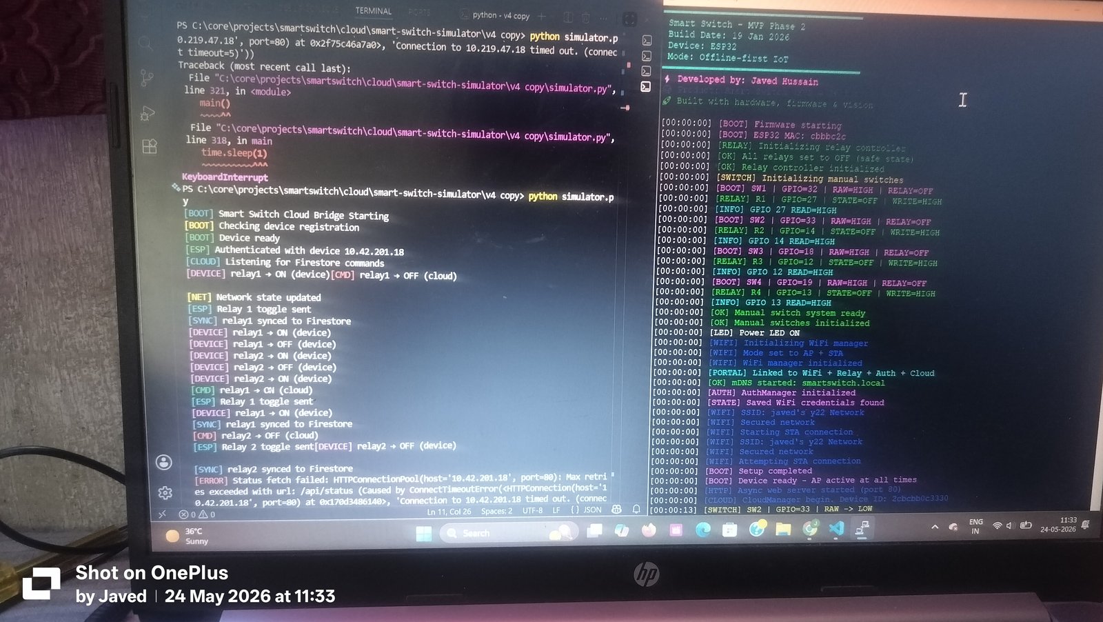
Debug-Grade Serial Logging
In logger.cpp, I created a categorized logging framework that prefixes serial output with colorized subsystem tags:
[BOOT]: Firmware startup sequence, MAC address detection, partition layout.[RELAY]: Relay index, target pin, requested logical state, output voltage level.[SWITCH]: Raw pin edge transitions, debounced stable confirmation.[WIFI]: AP mode initialization, STA connection attempts, RSSI metrics.[INFO]: Hardware read-back verification confirming that physical voltage levels match software expectations.
Python Cloud Bridge Simulation
In Phase 2 development, I explored extending Smart Switch toward remote cloud capabilities. To test how the ESP32 handles bidirectional synchronization without relying on third-party proprietary clouds, I built a local Python simulator (simulator.py) that interfaces with Google Firestore. As shown in Figure 5, the bridge listens for remote command events, forwards them to the device REST API, and updates real-time Firestore documents whenever a manual wall switch is flipped.
Firmware Security & Reverse Engineering Auditing
As an engineering student with a strong passion for cybersecurity, I wanted to understand how secure IoT devices actually are in the field.
Most commercial smart-switch manufacturers ship devices with unprotected flash memory, allowing attackers with physical access to extract firmware binaries, recover Wi-Fi credentials, and reverse engineer proprietary protocols.
To evaluate this firsthand, I set up a dedicated firmware security lab:
- Using the
esptool.pyutility, I extracted raw flash binary images from the ESP32:bootloader.bin,partitions.bin, andfirmware.bin. - I loaded
firmware.elfand decompiled binary symbols into Ghidra, the open-source software reverse engineering suite. - By analyzing function calls, memory maps, and string tables in Ghidra, I audited how sensitive data (such as Wi-Fi credentials in NVS and API authentication tokens) was represented in memory.
This security auditing exercise reinforced the vital importance of enabling ESP32 Flash Encryption and Secure Boot v2 before deploying embedded devices in production environments.
From Breadboard Prototype to Custom PCB Design
A breadboard with jumper wires is acceptable for proving firmware logic on a workbench. However, breadboards are fundamentally unsafe for permanent installation inside a wall cavity. Jumper wires loosen over time, exposed pins risk accidental shorts, and high-voltage AC conductors must never share a flimsy prototype board with delicate 3.3V logic.
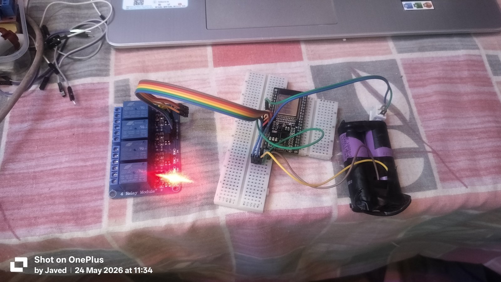
To transition Smart Switch toward a production-grade form factor, I developed a comprehensive 2-Layer Custom PCB Architecture:
1. Galvanic Separation & Physical Isolation Slots
On a custom PCB, the board is physically divided into two distinct zones:
- Low-Voltage Zone (DC): Houses the ESP32, 3.3V voltage regulation circuitry, status LEDs, and low-voltage screw terminals for the manual wall switches.
- High-Voltage Zone (AC): Houses the 230V AC mains input terminals, fast-blow fuses, relays, and load output screw terminals.
- Milled Isolation Slots: Physical air gaps (isolation slots) milled directly through the FR4 fiberglass substrate beneath the optocouplers and relay contact pads to eliminate surface creepage breakdown under high ambient humidity.
2. Onboard Isolated AC-DC Power Supply
Rather than powering the switch through an external micro-USB cable, the custom hardware design incorporates an embedded Hi-Link HLK-PM01 isolated AC-DC converter module:
- Ingests 90–264V AC household mains.
- Outputs a regulated, isolated 5V DC rail to power the relay coils and ESP32 3.3V LDO regulator.
- Features built-in thermal protection, short-circuit protection, and galvanic isolation rated up to 3000V AC.
3. Mains Protection Circuitry
To protect against voltage surges and lightning transients common on regional electrical grids, the input stage incorporates:
- A 2A Fast-Blow Fuse to disconnect mains current in the event of an internal short.
- A Metal Oxide Varistor (MOV - 14D471K) connected across Live and Neutral to clamp high-voltage spikes.
- A Flyback Diode (1N4007) across each relay coil to suppress inductive voltage kickback when the magnetic coil de-energizes.
Implemented vs. Designed vs. Planned
To maintain absolute technical integrity, here is the exact status of each capability across the Smart Switch project:
| Feature / Architecture Layer | Status | Technical Implementation Details |
|---|---|---|
| 4-Channel Active-LOW Relay Control | Implemented | Songle relays on GPIOs 27, 14, 12, 13 with safe-boot OFF enforcement |
| 4-Gang Physical Wall Switch Inputs | Implemented | Debounced mechanical inputs on GPIOs 32, 33, 18, 19 with INPUT_PULLUP |
| Boot-Time Deterministic State Sync | Implemented | Reads physical switches at boot; eliminates power-cut relay chatter |
| Local Captive Portal & Web Dashboard | Implemented | Async web server on port 80; controls relays at 192.168.4.1/dash |
| Local Network mDNS Resolution | Implemented | Resolves to http://smartswitch.local on home Wi-Fi network |
| NVS Persistent State Storage | Implemented | Saves Wi-Fi credentials and preferences using ESP32 Preferences library |
| Modular PlatformIO C++ Codebase | Implemented | Structured separation of config, control, core, network, and system layers |
| Firmware Reverse Engineering Audit | Implemented | Binary dumps analyzed in Ghidra for credential exposure testing |
| Custom 2-Layer PCB & AC-DC Power | Designed | Isolation slots, HLK-PM01 AC-DC module, fuse + MOV protection layout |
| HLW8032 Energy Monitoring | Planned | Current and voltage sensing IC for future energy analytics |
| BLE Mobile Provisioning | Planned | Native mobile onboarding over Bluetooth Low Energy |
Mains Safety Considerations
Working with mains electricity is serious. 230V AC can cause severe injury, electrocution, and electrical fires if handled carelessly.
Throughout this project, I maintained strict safety protocols:
- Zero AC on the Microcontroller: The ESP32 and physical wall switches operate exclusively on low-voltage DC signals (3.3V / 5V). At no point does alternating current pass through the wall switch lines or ESP32 GPIOs.
- Galvanic Optocoupler Isolation: The relay board uses optical transmission—an infrared LED illuminating a phototransistor across an air gap—ensuring no electrical path exists between high-voltage contacts and low-voltage logic.
- Proper Enclosures Required: A prototype on a desk must never be installed inside a home wall cavity without a flame-retardant, properly rated electrical junction enclosure.
This build story is an engineering case study in embedded systems design, not a casual DIY electrical guide.
What I Learned Building Smart Switch
Building Smart Switch taught me lessons that software tutorials and simulator tools never reveal:
- Hardware Dictates Software Architecture: You cannot write clean embedded code in an abstract vacuum. Hardware quirks—such as floating inputs on GPIO 34–39, contact bounce on mechanical toggles, and active-LOW relay polarities—directly shape how your C++ state machines must be structured.
- Offline-First Is Not Optional in IoT: The moment an IoT device fails because an internet server is down, it ceases to be useful. Designing systems that work locally by default creates products that users can genuinely trust.
- Debugging Requires Full-Stack Visibility: From testing lithium battery voltage sag with a multimeter to inspecting serial telemetry at 115200 baud and auditing binary firmware dumps in Ghidra, building hardware forces you to master every layer between physical electrons and application code.
Conclusion
Smart Switch started as a desire to build something tangible—a project that crossed the boundary between lines of code and real, clicking electrical hardware.
By combining the processing power of the ESP32, the reliability of active-LOW relays, a deterministic boot synchronization algorithm, and a local captive portal web interface, it evolved from early battery experiments into a robust, working home automation prototype.
Building it reinforced my belief that great engineering isn't about making devices that look flashy on a cloud dashboard; it's about making systems that work every single time someone flips a switch on the wall.
Explore Smart Switch & Related Work
- Project Case Study: Smart Switch Technical Architecture & Overview
- About the Builder: About Javed Hussain
- Technical Skills Matrix: Explore Embedded, IoT & Cybersecurity Skills
Written by Javed Hussain • Last updated on 2026-03-15