Overview
Smart Switch is an embedded IoT home automation system designed and built by Javed Hussain. Unlike conventional smart-home products that become unresponsive when the internet drops or cloud servers experience downtime, Smart Switch is engineered with an uncompromising offline-first philosophy: physical household wall switches retain absolute reliability and control, while local Wi-Fi and web capabilities serve as an enhancement rather than a point of failure.
Built around the ESP32 microcontroller and a 4-channel active-LOW relay module, the system interfaces directly with traditional residential toggle switchboards, providing instant mechanical switching alongside responsive local network controls.
Project Metadata
- Category: Embedded Systems / IoT / Hardware Prototyping
- Status: Completed Working Prototype (MVP v1 – v4)
- Controller: Espressif ESP32 Dev Module (ESP32-WROOM-32)
- Firmware Framework: C++ / PlatformIO (Arduino Core for ESP32)
- Author / Developer: Javed Hussain (
@iamjaved026) - Primary Focus: Offline-First Switching, Boot-Time State Synchronization, Hardware Isolation, Local Captive Portal
Why I Built It
Most commercial smart switches available on the market suffer from fundamental architectural flaws:
- Cloud Dependency: If the home Wi-Fi router restarts or the cloud provider experiences an outage, lights and appliances cannot be toggled.
- Ignoring Physical Wall Switches: Many smart modules force users to use an app or voice assistant, confusing family members who naturally reach for the wall switch.
- Power-Cut Glitching: When electricity returns after a blackout, poorly designed microcontrollers often cycle relays randomly, turning every connected light ON in the middle of the night.
Living in Teghra, Bihar, where intermittent power interruptions and network fluctuations occur, I set out to build a smart switch that feels as instant, tactile, and trustworthy as a traditional mechanical switch, while adding modern wireless convenience.
Hardware Architecture & Physical Test Rig
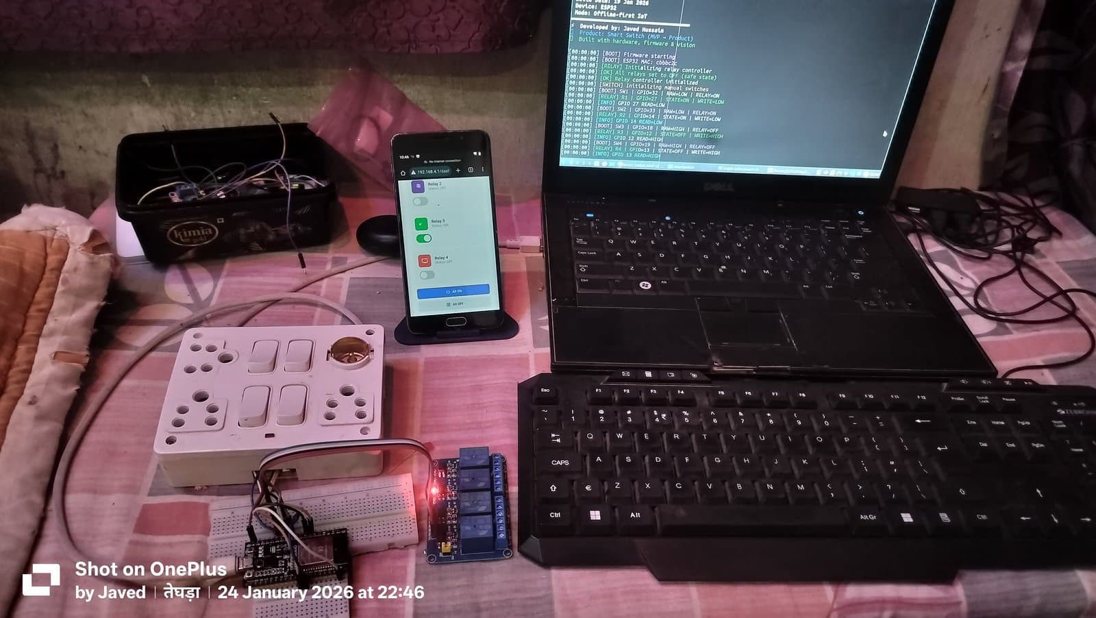
The prototype was constructed and validated using a dedicated desktop test bench that mimics a real Indian household switchboard:
- Microcontroller: ESP32 Dev Module with 30-pin layout, dual-core Xtensa 32-bit LX6 processor.
- Relay Board: 4-Channel Active-LOW Relay Module utilizing Songle SRD-05VDC-SL-C electromechanical relays (rated up to 250V AC / 10A), optocoupler isolation, and red channel indicator LEDs.
- Physical Switch Interface: 4-gang Indian modular wall switchboard with traditional mechanical toggle switches, connected to ESP32 inputs with low-voltage signal wiring and common GND.
- Status Indication: Low-voltage status LED on GPIO 15 with current-limiting resistor.
- Power Provisioning: Dual-rail testing with 5V USB for logic development and an external 2x 18650 Li-ion battery pack for decoupled testing.
Signal & Control Flow Architecture
  [ Physical Wall Switches ] ────────┐
  (4x Mechanical Toggles)            │
                                     ▼
                        [ ESP32 Microcontroller ]
                        ┌───────────────────────────────┐
  [ Local Smartphone / Web ] ──►│ Debounce Engine (millis())    │
  (192.168.4.1/dash Portal)     │ Boot-Time State Sync Logic    │
                                │ NVS State Memory Storage      │
                                └──────────────┬────────────────┘
                                               │ (Active-LOW Logic)
                                               ▼
                                  [ 4-Channel Relay Board ]
                                  (Optocoupler Galvanic Isolation)
                                               │
                                               ▼
                                   [ 230V AC Household Loads ]
                                   (Fans, Lights, Appliances)
GPIO Pin Assignment & Safety Engineering
Selecting GPIO pins on the ESP32 requires careful attention to hardware constraints. During development, critical design rules were established to prevent ghost signals and boot failures:
| Component | Pin Function | ESP32 GPIO | Electrical Mode | Engineering Notes |
|---|---|---|---|---|
| Switch 1 | Manual Wall Switch 1 | GPIO 32 | INPUT_PULLUP | Low-voltage signal line (Yellow wire) |
| Switch 2 | Manual Wall Switch 2 | GPIO 33 | INPUT_PULLUP | Low-voltage signal line (Green wire) |
| Switch 3 | Manual Wall Switch 3 | GPIO 18 | INPUT_PULLUP | Low-voltage signal line (Orange wire) |
| Switch 4 | Manual Wall Switch 4 | GPIO 19 | INPUT_PULLUP | Low-voltage signal line (Blue wire) |
| Common GND | Switch Common Reference | GND | Ground | White common wire connecting all 4 switches |
| Relay 1 | Channel 1 Driver | GPIO 27 | OUTPUT | Active-LOW trigger (LOW = ON, HIGH = OFF) |
| Relay 2 | Channel 2 Driver | GPIO 14 | OUTPUT | Active-LOW trigger (LOW = ON, HIGH = OFF) |
| Relay 3 | Channel 3 Driver | GPIO 12 | OUTPUT | Active-LOW trigger (LOW = ON, HIGH = OFF) |
| Relay 4 | Channel 4 Driver | GPIO 13 | OUTPUT | Active-LOW trigger (LOW = ON, HIGH = OFF) |
| Status LED | System Status Indicator | GPIO 15 | OUTPUT | Current-limited LED indicator |
| Boot Button | Factory Reset / AP Mode | GPIO 0 | INPUT | Hardware boot button / recovery trigger |
Critical Hardware Learning: GPIO 34–39 on the ESP32 are input-only pins and lack internal pull-up/pull-down resistors. Attempting to use them for switch inputs without external pull-up resistors causes floating, noisy inputs. They were intentionally excluded from switch duties in favor of GPIOs 32, 33, 18, and 19.
Key Capabilities & Firmware Features
1. Deterministic Boot-Time State Synchronization
When power is restored after an electrical cut, the ESP32 initializes all relay pins to HIGH (the safe, non-energized state for active-LOW relays) to eliminate boot-time clicking. Within milliseconds, the firmware reads the actual physical position of each wall toggle switch and immediately commands the relays to match:
- Switch physically ON ➔ Relay energizes ON.
- Switch physically OFF ➔ Relay remains OFF.
- No unexpected light toggles in the middle of the night.
2. Non-Blocking Debouncing Engine
Mechanical wall switches produce electrical contact bounce (microsecond noise spikes) when toggled. The firmware implements a non-blocking debouncing algorithm using millis():
- Detects raw pin state transitions instantly.
- Waits for signal stability across a configurable debounce threshold before committing state updates.
- Eliminates ghost toggling caused by nearby electromagnetic interference (EMI) or arcing.
3. Onboard Captive Portal & Web Dashboard
The ESP32 runs an embedded asynchronous HTTP server (ESPAsyncWebServer) that serves a complete HTML5/CSS3 control dashboard directly from flash memory:
- AP Mode Provisioning: Broadcasts a local Wi-Fi hotspot (
SmartSwitch-AP) allowing any smartphone to connect directly at192.168.4.1/dashwithout needing internet access. - Interactive Toggles: Individual switches for Relays 1 through 4, accompanied by master "All ON" and "All OFF" actions.
- Network Scanner: The
/api/wifi-scanendpoint scans local 2.4 GHz networks, reporting SSIDs, signal strengths (RSSI), and encryption types to facilitate wireless configuration. - Local Network mDNS: Once connected to the home router, the device resolves automatically to
http://smartswitch.local.
4. Read-Back Verification & Serial Telemetry
Every relay command is verified in hardware. After executing a digitalWrite, the firmware immediately reads the pin's state back via digitalRead and outputs formatted telemetry over the serial interface at 115200 baud, enabling transparent debugging of electrical behavior.
Development Evolution: From Prototype to Product Thinking
The project progressed across multiple disciplined engineering iterations:
- MVP v1 (19 Jan 2026): Proved the offline-first foundation. Implemented 4 physical wall switches, 4-channel active-LOW relay driver, boot-time state sync, and strict serial logging.
- MVP v2 (20 Jan 2026): Added Non-Volatile Storage (NVS) memory support via the ESP32 Preferences library to persist relay states and user preferences across reboots.
- MVP v3 (24 Jan 2026): Introduced the onboard captive portal, local network web dashboard (
192.168.4.1/dash), and asynchronous REST API endpoints for wireless phone control. - MVP v4 (Feb–Mar 2026): Engineered multi-network management, device authentication tokens, watchdog timer recovery, and an experimental Python Firestore cloud bridge simulator for remote synchronization.
- Firmware Security Auditing: Extracted raw firmware binaries (
bootloader.bin,firmware.bin,firmware.elf) and conducted reverse engineering disassembly testing using Ghidra to understand IoT attack surfaces and memory protection.
Implemented vs. Designed vs. Planned
| Feature | Status | Verification & Evidence |
|---|---|---|
| 4-Channel Active-LOW Relay Control | Implemented | Verified in firmware (relay_controller.cpp) and live bench test rig |
| 4 Physical Wall Switches with Debouncing | Implemented | Verified in firmware (manual_switch.cpp) with home switchboard |
| Boot-Time State Sync Logic | Implemented | Tested across power-cycle simulations in PlatformIO serial logs |
| Local Captive Portal & Web Dashboard | Implemented | Working live at 192.168.4.1/dash on smartphone |
| Wi-Fi STA Connection & mDNS Resolution | Implemented | Verified connecting to home router and resolving smartswitch.local |
| NVS Non-Volatile Storage for State | Implemented | Verified in nvs_manager.cpp storing Wi-Fi and relay states |
| PlatformIO Modular C++ Architecture | Implemented | Production codebase with separated config, control, and core layers |
| Reverse Engineering Security Audit | Implemented | Binary firmware extracted and analyzed with Ghidra |
| Custom 2-Layer PCB Layout & Manufacturing | Designed | High-voltage isolation slots, HLK-PM01 AC-DC power, MOV protection |
| HLW8032 / PZEM Energy Monitoring | Planned | Hardware design consideration for Phase 3 iteration |
| BLE Provisioning via Native Mobile App | Planned | Roadmap feature for consumer-friendly Wi-Fi onboarding |
Mains Safety & High-Voltage Isolation
Switching real 230V AC household electrical loads carries genuine safety considerations:
- Galvanic Isolation: The low-voltage ESP32 circuit (3.3V logic) is physically isolated from the high-voltage mains AC lines through the relay module's onboard optocouplers.
- Enclosure & Clearance: In practical deployment, mains-carrying conductors must reside inside flame-retardant enclosures with physical separation and creepage clearance slots separating high-voltage traces from low-voltage logic.
- Overcurrent Protection: The hardware architecture mandates an upstream fast-blow fuse and Metal Oxide Varistor (MOV) for transient voltage surge suppression.
Explore the Build Story & Architecture
- Developer Build Story: Building My ESP32 Smart Switch: From Prototype to Custom Hardware
- About the Builder: About Javed Hussain
- Technical Skills Matrix: Explore Embedded & IoT Skills